
I’m not sure what lead you here, but if you just want the code to be able to connect an Atari controller to a computer, using an Arduino Micro, head on over to my GitHub project. If you want to learn more about how I worked through this project, read on.
If you have any questions, comments or feedback, leave them below!
Introduction
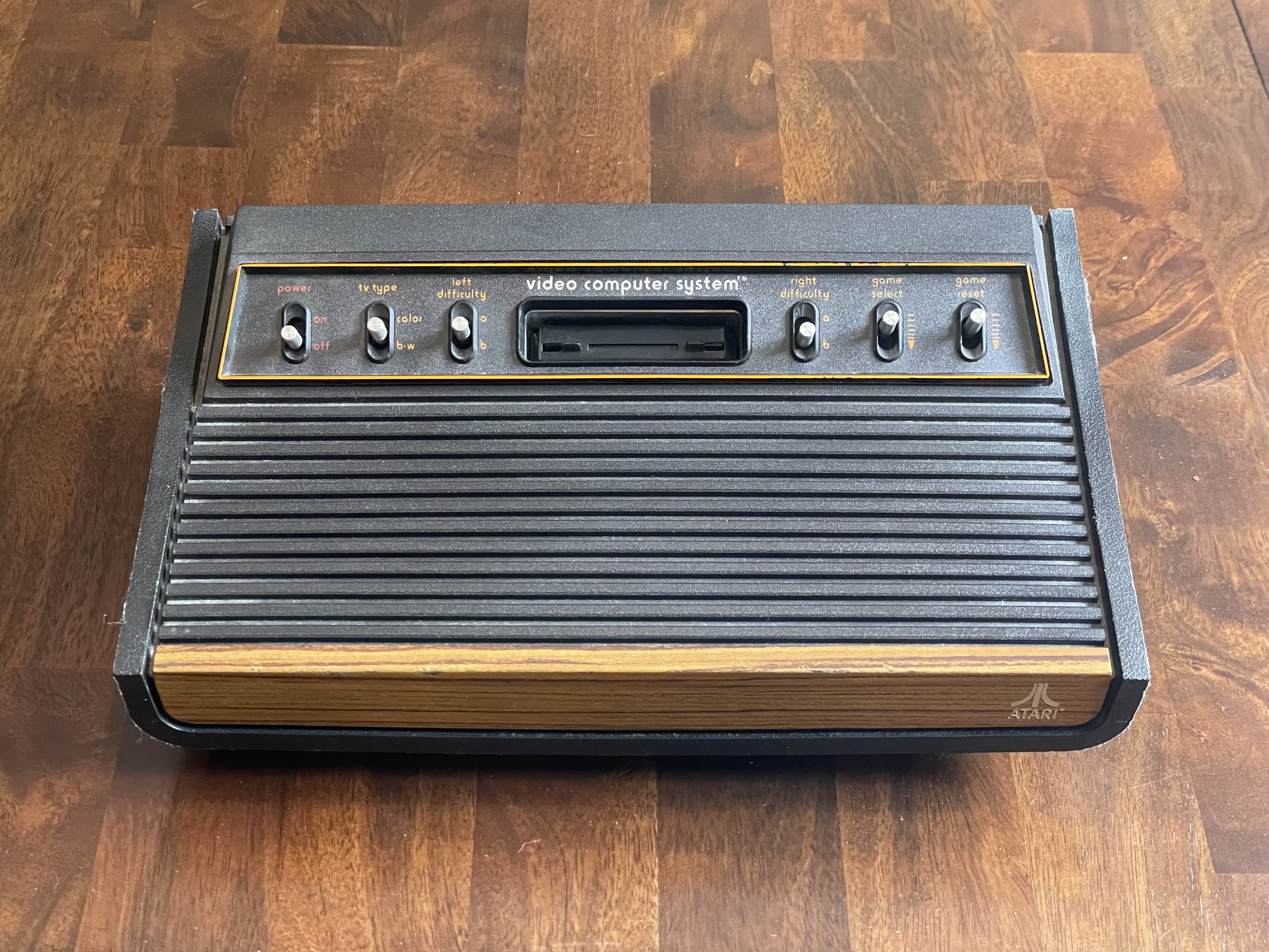
The Atari was my first video game system and I still enjoy the games to this day. Given I also like technology, I’ve been very interested in the approachability of the Atari, the controls and the 6502 chip. Where the complexity of a modern game or gaming machine is nearly incomprehensible, the Atari is much more approachable.
Another interest I’ve had is where hardware meets software. Because of this interest, I was looking for a project to use an Arduino. Putting all these interests together, I decided to create a project tha would allow me connect my real CX-40 Atari joystick to my modern computer to play the Atari emulator, Stella.
To be clear, what I did is not unique, it has been done a millions times in a million different ways. In fact, I have a commerical (now discontinued) product called 2600-Daptor that does exactly what I’ve done in a nice professional package.
The original CX-40 Atari joystick has a straightforward vocabulary: up, down, left, right, and fire. It connects to the Atari with a simple DE-9, 9 pin, connector.
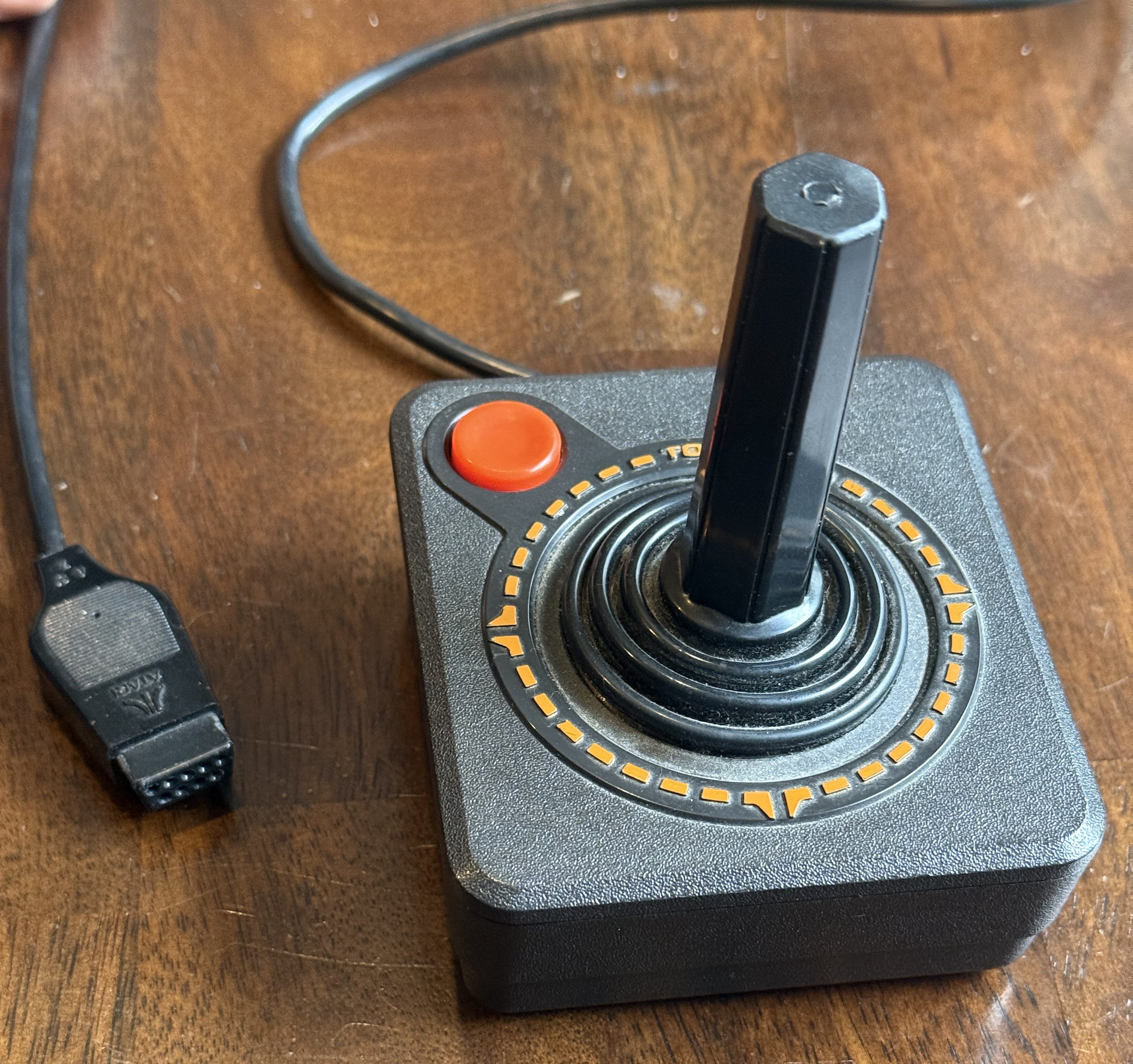
To solve this problem, I need to connect the controller’s male DE-9, to a female DE-9 that I could wire to an Arduino board. The Arduino board could then attach to the computer via USB.
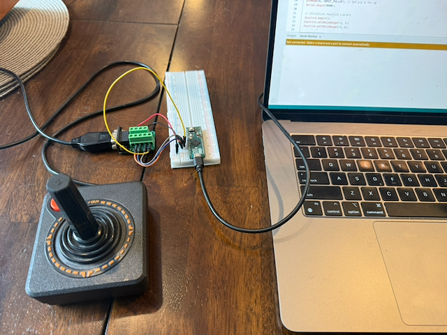
My Arduino Atari Controller project was about taking those inputs and building a bridge to USB, using an Arduino Micro and a DE-9 breakout connector.
The build brought together wiring, small Arduino programs, and a USB joystick library. But one of the most useful moments came before the USB work: the board could detect a connection when I shorted it directly, yet nothing happened when I used the joystick.
The explanation turned out to be in a screw terminal.
Parts list
These are the main parts I bought for the build, with the product links saved in my project notes:
- Arduino Micro — the board that reads the joystick inputs and connects to the computer over USB.
- DE-9 breakout connector — makes the joystick connector’s individual pins accessible through screw terminals.
- Solderless breadboard — holds the Arduino and provides a convenient way to prototype the connections.
The setup also uses connecting wires, a USB data cable, and my Atari CX-40 joystick.
Making a Connection
The first thing I needed to understand was how to connect the Atari controller to the Arduino board. I started with understanding the Atari side, the DE-9 connector.
DE-9 Connector
The Atari joystick connects through a DE-9 connector, a nine-contact member of the D-subminiature family developed by Cannon in 1952. Atari adopted this connector for the Video Computer System, later known as the Atari 2600, when it launched in 1977, and the design went on to become a common joystick interface on other home computers.
For the basic joystick, the wiring uses only six of the nine positions: four for direction, one for fire, and a shared ground. If you look closely at the end of my joystick’s connector, you can see that some holes have no metal contacts inside—the unused positions don’t need an electrical connection. Moving the stick or pressing fire closes the corresponding switch, which is what makes this controller such an approachable starting point for an Arduino project.

| Controller function | Atari DE-9 pin | Arduino Micro connection |
|---|---|---|
| Fire | 6 | D2 |
| Up | 1 | D3 |
| Down | 2 | D4 |
| Left | 3 | D5 |
| Right | 4 | D6 |
| Ground | 8 | GND |
The wiring used five digital inputs and a shared ground. Here is the mapping documented in the repository and used by the sketches:
| Controller function | Atari DE-9 pin | Arduino Micro connection |
|---|---|---|
| Fire | 6 | D2 |
| Up | 1 | D3 |
| Down | 2 | D4 |
| Left | 3 | D5 |
| Right | 4 | D6 |
| Ground | 8 | GND |
A small set of parts and a clear first goal
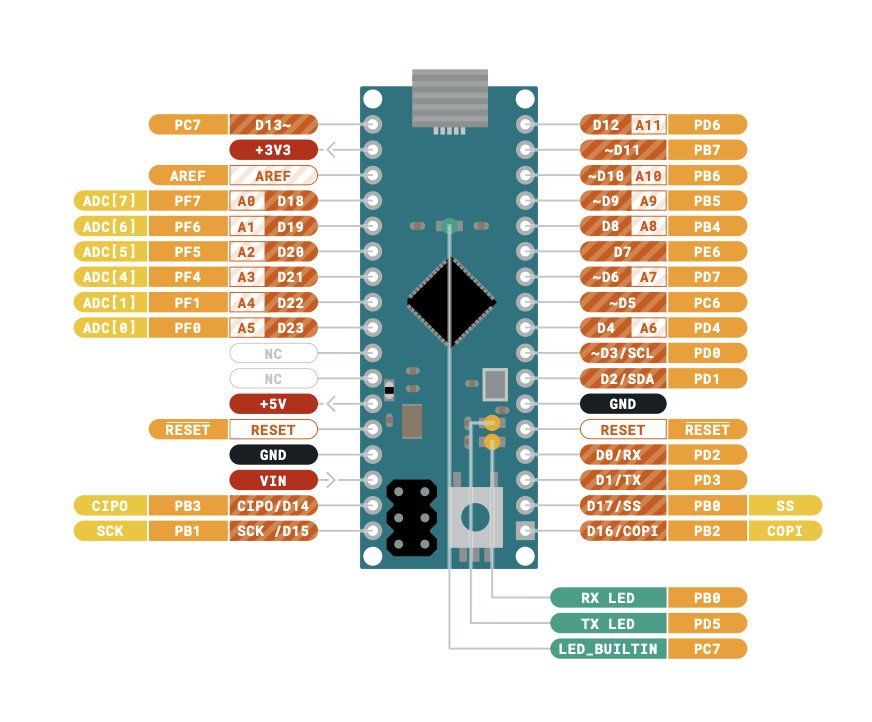
The hardware centered on an Arduino Micro, a breadboard, and a DE-9 breakout connector for the Atari controller. The breakout made the controller’s individual connections accessible to the Arduino.
I have never used an Aduino before and was not familiar with how to program it. The immediate goal was simple: read the fire button. Once that worked, the same approach could be extended to the four directions. USB reporting added another layer, translating those physical inputs into gamepad controls.
void setup() { // put your setup code here, to run once: pinMode(2, INPUT_PULLUP); // Set pin 2 for button Serial.begin(9600); } String button = "Released";void loop() { // put your main code here, to run repeatedly: int Fire = digitalRead(2); // Serial.println(Fire); // delay(1000); if (Fire == 0 && button == "Released") { // Use "&&" instead of "and" button = "Pressed"; Serial.println(button); } else if (Fire == 1 && button == "Pressed"){ button = "Released"; Serial.println(button); } }
The project README collects the hardware references, pinout diagrams, wiring map, and joystick-library setup instructions.
The first obstacle: a button that would not register
My journal entry for August 24, 2026 captures the first debugging session. The Arduino could read an input when I shorted the connection, but it could not read it through the joystick and breakout.
That observation helped narrow the problem. A direct connection produced a response, so the next place to look was the physical path between the controller and the board. I checked continuity in the connector, which was OK, and then moved on to the breakout.
The problem was the breakout terminal: it had been screwed the wrong way. After correcting that, I was able to write the first program to detect a fire-button press.
It was a small fix, but a useful lesson from the build. Before changing the program, check whether the signal can actually reach it. The build journal records that breakthrough, along with my first notes about learning debouncing.
The repository’s Atari pinout is shown from the front of the console-side port. That viewing direction matters when matching the diagram to the connector; the pin numbers are the reference to follow.
The sketches configure the inputs with INPUT_PULLUP. In this arrangement, an idle input reads high, and an activated control pulls the input to ground so it reads low. In the program, that means 0 represents a pressed button or an active direction.
That detail becomes especially useful later, when translating a physical button press into a USB gamepad event.
Building the software in manageable pieces
The repository preserves several small sketches, each tackling a different part of the interface. Together, they show how the project can be understood one layer at a time.
Reading the fire button
The ButtonTest sketch reads D2 and prints a message when the fire button changes state.
It keeps track of whether the button was previously pressed or released. That lets it print a new message only when something changes, making the output easier to follow than a continuous stream of identical readings.
This was the smallest useful test: one physical input, one state change, and a visible response in the Serial Monitor.
Adding the four directions
The ReadButtonAndDirections sketch extends that pattern to all five inputs. It reports when each direction starts and stops, alongside the fire-button messages.
This creates a way to check the controller wiring before involving USB gamepad behavior. Each control has its own readable response.
One unexpected lesson was something called switch bounce. I had assumed that pressing a button produced one clean electrical change. In reality, the controller’s mechanical contacts can briefly make and break contact as they settle, and the Arduino can read those rapid changes as multiple transitions from a single press. What felt like one action in my hand could look like several events in software. This was the physics of the controller showing up as an issue I had to resolve in the program—a process called debouncing. I would never have realized this was happening if this project hadn’t taken me into the interface between hardware and software.
The sketch includes a 20-millisecond delay labeled as debouncing. The delay slows the polling as a simple first measure, though it does not implement a full check that an input has remained stable for a specified time.
Testing the USB side separately
The JoystickBasicButtonTest sketch isolates another part of the problem. It initializes a USB gamepad, waits, sends a button press, and then releases it without reading the Atari controller.
That separation is useful: the physical input test checks the controller and wiring, while the basic USB test exercises gamepad reporting on its own.
The USB sketches use MHeironimus’s Arduino Joystick Library, which the project README includes instructions for installing.
Bringing the inputs and USB interface together
The JoystickUSBInterface sketch brings input reading and USB reporting into the same program. It configures a gamepad with one button and X and Y axes, with each axis assigned a range of -1 to 1.
The fire-button conversion is particularly compact:
Joystick.setButton(0, !Fire);
The physical input reads 0 when pressed, while the gamepad button needs a true value for a press. The ! operator flips the reading to make those conventions agree.
In the version currently committed to the repository, right movement sets the X axis to 1, and releasing it returns that axis to 0. All four directions are read and reported through serial diagnostics, but left, up, and down are not yet mapped to USB axis updates in that file.
That is the distinction between the wiring milestone and the published firmware snapshot: the README includes a “Final Product” photograph, while the committed USB sketch preserves a partial direction mapping.
What this build taught me
The most concrete lesson was the first one: a connection problem can look like a programming problem. Being able to trigger the Arduino directly gave me a useful comparison, and checking continuity led me back to the breakout terminal.
The other lesson is visible in the collection of sketches. A controller interface becomes easier to understand when each piece has a small, observable test: detect one button, read the directions, generate a USB button event, and then combine the pieces.
That makes the repository useful as a record of the build. It captures the wiring decisions, the first successful input, and the steps toward translating an Atari controller into a USB gamepad.
Explore the project
The wiring references, Arduino sketches, build journal, and final wiring photograph are available in my Arduino Atari Controller repository on GitHub.


Leave a comment