
A Familiar Problem
I’ve been using the Logitech MX Vertical mouse for years. After spending so much time using a traditional mouse, I started experiencing wrist pain and switched to the MX Vertical as a more ergonomic alternative. I’ve been very happy with it, but I’ve now encountered the same frustrating problem twice.
The mouse would occasionally fail to register a click, or, most annoyingly, release a click while I was still holding the button down. If you’ve ever tried dragging a file or selecting text only to have the mouse suddenly let go, you know how frustrating this can be.
What made this particularly annoying was the sense of déjà vu. I had experienced exactly the same problem with another MX Vertical a year or two earlier and eventually replaced the mouse.
Rather than buying a third one, I decided to do a little research.
It turns out I’m far from the only person who has experienced this issue. Other MX Vertical owners have reported similar problems with the mechanical microswitches beneath the mouse buttons. Over time, the electrical contacts inside these switches can deteriorate, resulting in missed clicks, unintended double-clicks, or interruptions when holding a button down.
During my research, I came across an excellent iFixit guide to replacing the MX Vertical’s microswitches, written by May D.
The instructions were detailed, with photographs documenting nearly every step. Better yet, the solution involved replacing the existing switches with new ones rather than replacing the entire mouse.
This project appealed to me for a couple of reasons. First, I’m already quite familiar with microswitches from my experience with arcade machines. Although the switches used in a mouse are considerably smaller, the underlying concept is the same.
More importantly, it involved soldering, something I’d been wanting to try for some time.
I’d recently started putting together a basic electronics repair toolkit, and this seemed like the perfect opportunity to put it to use. The mouse was already essentially broken, so I figured I didn’t have much to lose if the repair didn’t work out.
Preparing for the Repair
Although I’m comfortable taking apart electronics, my soldering experience was extremely limited. Before getting started, I spent some time researching the tools and supplies I’d need and watching YouTube videos demonstrating basic soldering and desoldering techniques.
I also enlisted the help of ChatGPT to research the equipment and parts I’d need.
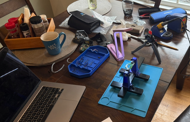
Here’s the equipment I assembled for the project:
| Tool or Supply | What I Used |
|---|---|
| Soldering station | Hakko FX-888D |
| Replacement microswitches | Omron D2F-01F |
| PCB Holder / Helping Hands | Pro’sKit SN-390 PCB holder |
| Solder | Kester 44 Rosin-Core, 63/37, 0.020″ |
| Flux | Chip Quik CQ4LF No-Clean Flux Pen |
| Desoldering pump | Spring-loaded solder sucker |
| Desoldering braid | Copper solder wick |
| Tip cleaner | Brass wool, included with the Hakko station |
| Screwdrivers | Precision Phillips-head screwdrivers |
| Plastic spudger | For separating components and releasing connectors |
| Cleaning supplies | 91% isopropyl alcohol and cotton swabs |
| Replacement mouse feet | Corepad Skatez for Logitech MX Vertical |
The iFixit guide identifies the original microswitches as Omron D2FC-F-7N(10M), which have a nominal rating of 10 million clicks. The guide’s author replaced them with D2FC-F-K(50M) switches, which are nominally rated for 50 million clicks.
However, those weren’t the switches I ended up using.
After discussing the options with ChatGPT, I selected Omron D2F-01F microswitches, which were available from DigiKey. These are a different Omron switch family from those used in the iFixit guide, but they turned out to work perfectly in my mouse.
I also purchased replacement mouse feet before beginning the repair. The iFixit guide warned that the original adhesive feet might be damaged during removal, so I wanted to have replacements available.
I found a set of Corepad Skatez replacement feet on eBay designed specifically for the MX Vertical.
Taking Apart the Mouse
Disassembling the MX Vertical was fairly straightforward. There are quite a few components to remove before reaching the circuit boards, but nothing was particularly difficult or outside my previous experience working with electronics.
I followed the iFixit guide closely, so I’m not going to attempt to reproduce its instructions or photographs here. Instead, these are some observations from my own experience.
Removing the Mouse Feet and Base
The first step was to turn off the mouse and remove the adhesive sliders, or mouse feet, from the bottom. These cover the screws that hold the two halves of the mouse together.
I tried to remove them carefully in the hope of reusing them, but the sliding material separated from the adhesive backing. Fortunately, I’d anticipated this and already ordered replacements.
With the feet removed, I was able to access the five Phillips-head screws holding the base and upper shell together.
Once those screws were out, I carefully separated the two halves of the mouse.
Disconnecting the Ribbon Cables
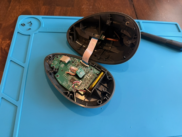
The upper and lower halves are connected by a delicate ribbon cable. To completely separate them, I needed to release the cable from its connector.
Using my plastic spudger, I gently lifted the cream-colored locking mechanism and slid the ribbon cable out.
This was my first encounter with what would become a recurring theme during the disassembly: small ribbon cable connectors with locking mechanisms that need to be released before the cables can be removed.
These connectors aren’t particularly complicated once you understand how they work, but they do require some care.
Removing the Upper Shell and Buttons
Next, I removed the five screws securing the rubberized hand-grip cover to the upper shell.
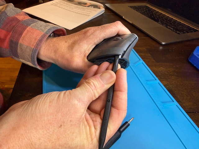
With those screws removed, I used the spudger to gently release the cover from the plastic clips holding it in place.
Removing the cover exposed four screws securing the left and right mouse buttons to the shell. After removing those, I could detach the buttons.
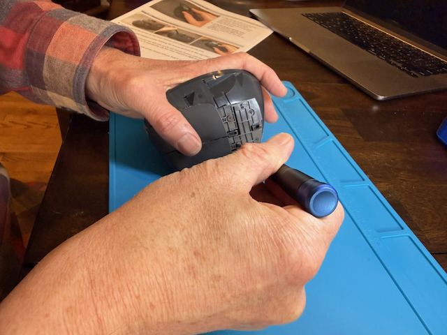
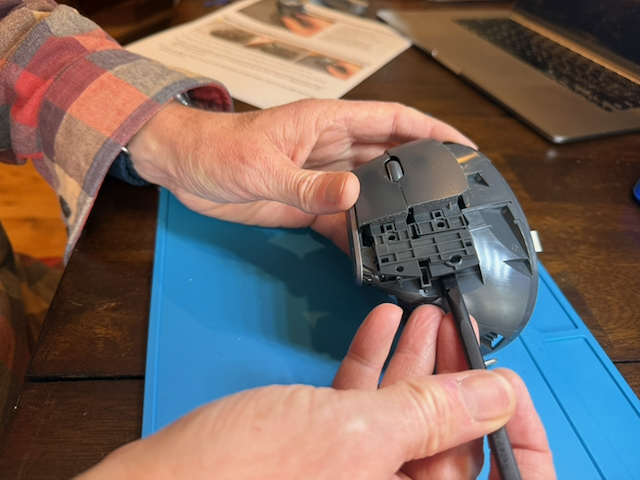
I then removed another four screws securing the scroll-wheel assembly and carefully lifted it out.
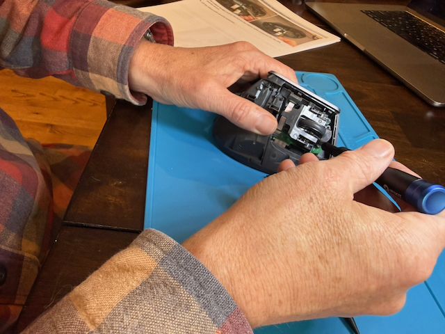
Next came a reddish ribbon cable connecting the DPI-switching button to the main circuit board. As with the previous cable, I released its connector before removing it. I had to take note of which way the ribbon cable was installed for re-installation later (lettering facing down)
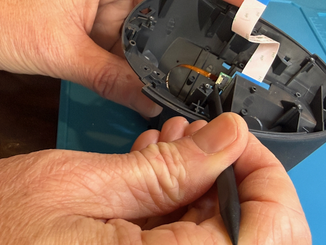
Removing the Circuit Boards
One interesting aspect of the MX Vertical’s construction is that the left mouse button has its own small circuit board, separate from the main board.
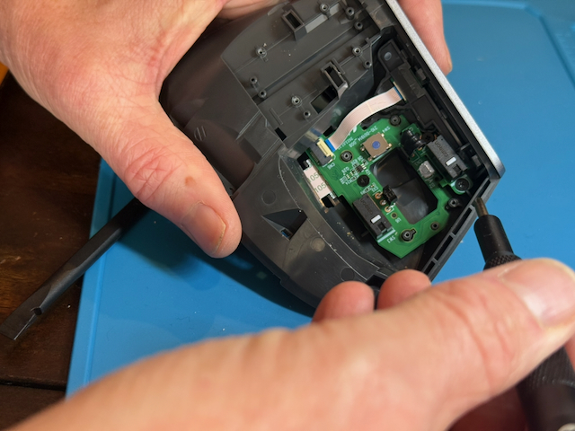
I removed the two screws holding this smaller board to the chassis and carefully moved it out of the way, taking care not to damage its connection to the main board.
There was then one screw securing the main circuit board to the chassis.
After removing that screw and disconnecting the ribbon cable for the navigation buttons, I was able to lift the main board out.
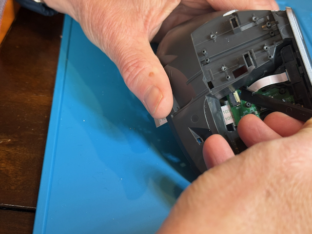
After getting the board out, one final ribbon cable needed to be disconnected from the board itself. I noted that the “T” shape on the ribbon cable connected to the board side.
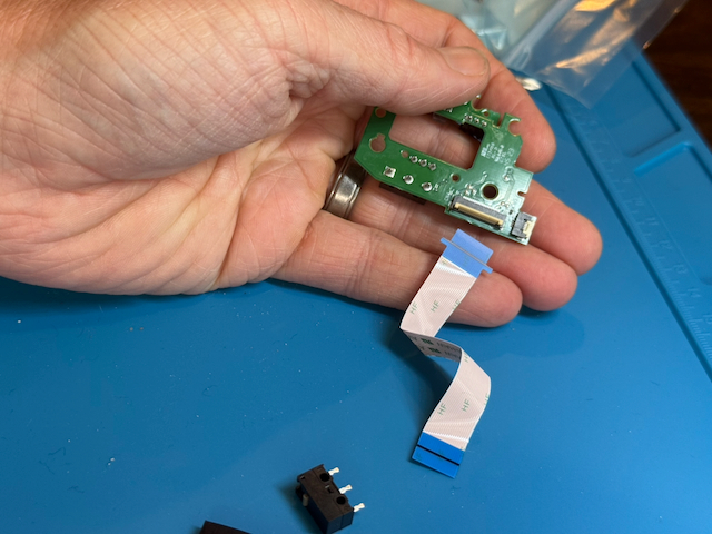
At this point, I’d finally reached the components I actually needed to repair.
Now came the part I’d been looking forward to, and, as it turned out, the most challenging part of the project.
Desoldering the Original Microswitches
This was my first real soldering project, and this was a challenging first soldering project.
The components were small, the solder joints were fairly close together, and I was still learning how to use the tools.
Each microswitch has three metal pins soldered through holes in the circuit board. To remove a switch, all three pins need to be freed from the solder holding them in place.
Without this repair the mouse was basically toast anyway so I could have probably picked an easier first project. I knew going in this wasn’t going to be easy, but given the condition of the mouse, I really couldn’t have made things worse.
Mounting the Board
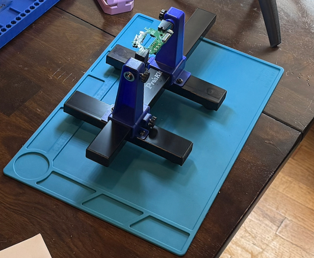
Before I could get started with soldering, I had to make sure the board was securely mounted because the desoldering/soldering was going to take 2 hands. I used my new PCB holder (Pro’sKit SN-390 PCB holder)
Finding the Right Temperature
I started with my Hakko FX-888D soldering iron set to approximately 350°C (662°F).
My new Kester solder melted almost immediately when I touched it to the iron, but the original solder on the circuit board was another story. It took much longer to heat up, and I had difficulty getting it to melt consistently.
I suspect the original solder was lead-free, which generally has a higher melting temperature than the 63/37 leaded solder I was using. The circuit board and switch pins also draw heat away from the joint, making heat transfer an important factor.
After some research and experimentation, I increased the iron temperature to 370°C (698°F).
This helped, although I eventually learned that temperature wasn’t the only issue. Getting good thermal contact between the iron, solder, and component was just as important.
Using the Solder Sucker
My first approach involved using a solder sucker, also called a desoldering pump.
The process was straightforward:
- Place the soldering iron against the switch pin and surrounding solder pad.
- Wait until the solder visibly melts and becomes shiny.
- Position the solder sucker directly over the molten solder.
- Trigger the pump to pull the solder away from the joint.
I was genuinely impressed by how well this worked. The first time I triggered the pump, it removed a surprising amount of solder.
Unfortunately, removing most of the solder wasn’t quite enough.
Despite repeated attempts, the switches remained firmly attached to the board. Even when I couldn’t see any more solder around the pins, they still wouldn’t come free.
I eventually learned why.
These switches use through-hole connections, meaning the pins pass through holes in the circuit board. The holes are plated with conductive material, and solder can remain inside them even after the visible solder has been removed from the surface.
A tiny amount of solder inside one of these holes is enough to keep the pin attached.
Discovering the Secret: Desoldering Braid and Flux
This was where copper desoldering braid, also called solder wick, came into play.
Initially, I wasn’t using it correctly. I tried heating the solder joint with the iron and then placing the braid against it, but that wasn’t particularly effective.
After doing a little more research, I learned that the proper technique was to create something of a sandwich:
Soldering iron → Copper braid → Solder joint
The braid goes directly against the solder joint, and the soldering iron is placed on top of it. Heat passes through the copper braid into the joint, melting the solder, which is then drawn into the braid by capillary action.
The braid visibly turns silver as it absorbs solder.
One important detail is that the iron and braid should be lifted away together while the solder is still molten. Otherwise, the braid can become soldered to the circuit board, creating another problem.
I also discovered something else I’d been overlooking: flux.
I already had a Chip Quik flux pen in my toolkit, but I hadn’t been using it consistently.
Once I started applying flux to both the solder joints and the braid, things improved considerably. Flux helps remove surface oxidation and allows molten solder to flow more readily.
Between the solder sucker, braid, and flux, I was finally making progress.
Even then, the switches weren’t immediately cooperating. I could see that the solder was melting, and the pins would occasionally wiggle slightly while hot, but they still wouldn’t release completely.
I continued patiently working each joint, alternating between the solder sucker and braid and gently checking whether the pins were free.
I was particularly careful not to force the switches out. Pulling too hard while a pin is still attached can lift a copper pad or damage the conductive traces on the circuit board.
Eventually, after quite a bit of trial and error, the first microswitch came free.
Success!
The Second Switch Was Much Easier
With the first switch removed, I’d learned several lessons that made the second one much easier.
This time, I started with the solder sucker to remove the bulk of the solder, followed by flux and desoldering braid to absorb what remained.
Rather than trying to force the switch out, I patiently worked the joints until the pins were free.
I managed to remove the second switch in probably half the time it had taken to remove the first one.
It’s remarkable how quickly something becomes easier once you understand the technique.
With both switches removed, I used 91% isopropyl alcohol and a cotton swab to clean the remaining flux residue from the circuit boards.
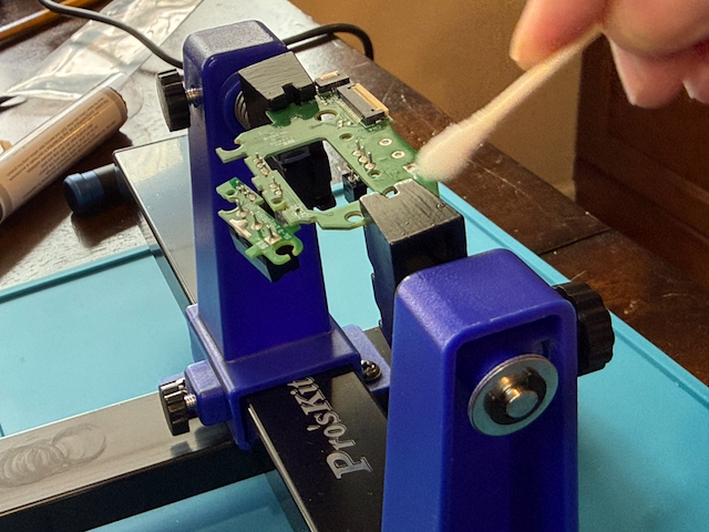
I also inspected the solder pads and holes to make sure they hadn’t been damaged during the process.
Installing the New Microswitches
After struggling through the desoldering process, installing the new switches was surprisingly easy.
One of the most useful things I’d learned from watching soldering tutorials was that you don’t melt solder onto the iron and drip it onto the connection.
Instead, you heat the component pin and the copper pad together, then touch the solder directly to the heated joint.
If the joint is hot enough, the solder melts and flows around the pin, forming the electrical connection.
I also learned that a little solder goes a long way. You don’t need a large blob covering the connection. Ideally, you want a smooth, properly wetted joint without excess solder.
I inserted the new Omron D2F-01F switches into their respective circuit boards, making sure they were correctly oriented and seated flat against the boards.
This is important because the physical position of the switch determines how the mouse button contacts it. If a switch sits too high or at an angle, the button may not operate correctly.
I soldered one pin first, verified the switch’s position, and then completed the other two connections.
After the difficulty of removing the original switches, I was pleasantly surprised by how straightforward this part of the job turned out to be.
A Few Other Things I Learned
Beyond the basic soldering and desoldering techniques, I picked up several useful lessons along the way.
Keeping the soldering iron tip clean matters. My Hakko station includes a brass-wool tip cleaner in its stand. Gently inserting the hot tip into the brass wool removes excess solder and residue without cooling the tip as much as a wet sponge. I also learned the importance of keeping a thin coating of fresh solder on the tip, called tinning, to protect it from oxidation.
More heat isn’t always the answer. When I first had trouble melting the factory solder, my instinct was to keep increasing the temperature. While a modest increase helped, proper contact, fresh solder, and flux made a bigger difference. Excessive heat can damage the board or lift its copper pads.
Desoldering is harder than soldering. At least, that was my experience. Installing the new components was relatively straightforward. Getting the old ones out without damaging anything required considerably more skill and patience.
Good tools make a difference. Before this project, I didn’t fully appreciate why someone would need both a solder sucker and desoldering braid. Now I understand that they complement each other. The pump works well for removing larger amounts of molten solder, while the braid is excellent for cleaning up the smaller amounts left behind.
Safety and cleanup matter, too. I learned to work with good ventilation to avoid breathing flux fumes, avoid touching my face while handling solder, and wash my hands afterward. It’s also important to disconnect power before working on a circuit board and allow any cleaning alcohol to evaporate completely before reconnecting the device.
How ChatGPT Helped Accelerate the Project
Another interesting aspect of this project was how much ChatGPT helped me along the way.
I’ve used ChatGPT for all sorts of research and technical questions, but this was a good example of how useful it can be when working on something physical, particularly when you’re learning a new skill.
Initially, I used it to help research the tools and supplies I’d need. It helped me select the soldering equipment, solder, flux, and replacement microswitches. That alone saved me quite a bit of time researching unfamiliar products.
But where it really became useful was during the repair itself.
When I couldn’t get the original solder to melt, I asked about the appropriate temperature for my soldering iron. When the switches still wouldn’t come loose, it helped me understand why the solder was so difficult to remove and suggested using desoldering braid and flux.
I could describe exactly what I was experiencing, get an explanation of what might be happening, and immediately try a different technique.
It also helped with smaller questions along the way, such as how to clean the soldering iron tip, how to use the brass-wool cleaner in the Hakko stand, and how to clean flux residue from the circuit board.
I probably could have fumbled my way through the project without ChatGPT, particularly with the excellent iFixit guide and the various soldering videos available online. But I’m fairly certain it would have taken me considerably longer.
Having something available to answer questions as they came up, without repeatedly searching through websites or watching videos, made the learning process much more efficient.
Of course, ChatGPT wasn’t holding the soldering iron, and its suggestions still required some judgment and experimentation on my part. But it was a useful resource for troubleshooting problems and understanding the techniques I was learning.
I think that’s one of the more interesting applications of AI: not necessarily doing the work for you, but helping you develop the knowledge and confidence to do it yourself.
Putting Everything Back Together
With the new microswitches installed, the remaining task was to reassemble the mouse.
Fortunately, the iFixit guide made this fairly easy. I simply followed the disassembly process in reverse, carefully reconnecting the ribbon cables and reinstalling the various circuit boards, buttons, scroll-wheel assembly, and outer shell.
I also replaced the original mouse feet with the Corepad Skatez replacements I’d purchased from eBay.
Once everything was back together, I tested the mouse.
It worked perfectly!
The missed clicks and frustrating click-and-drag failures were gone. The replacement Omron switches worked just as I’d hoped, and the mouse was back to normal.
After all the difficulty I’d had removing the original switches, having everything work correctly on the first attempt was particularly satisfying.
Final Thoughts
What started as an annoying problem with an expensive mouse turned into a very satisfying electronics repair project.
Rather than buying yet another MX Vertical, I was able to replace the components responsible for the problem. The replacement Omron switches are working perfectly, and I’m hopeful they’ll prove more durable than the originals.
But perhaps the more valuable outcome was what I learned along the way.
I’d been interested in learning how to solder for some time, and this project gave me a practical reason to do it. I now have some firsthand experience soldering and desoldering components from a printed circuit board, using flux, solder wick, and a desoldering pump.
More importantly, I have a much better understanding of why those techniques work.
A special thanks to May D, who created the excellent Logitech MX Vertical Microswitch Replacement guide on iFixit. The clear instructions and photographs made this project approachable for someone with very little soldering experience.
My intention with this article wasn’t to reproduce that guide, but rather to document my own experience, the challenges I encountered, and the things I learned along the way.
In the end, I got more than a repaired mouse out of the project. I gained some new skills, added a few useful tools to my workshop, and built a little more confidence in tackling future electronics repairs.
Not a bad outcome for a mouse that I was otherwise ready to throw away.


Leave a Reply